Note: The example above is for the BenchVue Power Meter bench application that provides single channel support. For the BenchVue Power Meter bench application that provides dual channel support, Channel A or Channel B will be displayed depending on the channel selected.
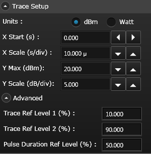
Trace Ref Level 1 - Enter the desired reference level for a proximal point for a Pulse Analysis configuration. Specify a value between 0 and 100% (default = 10%).
Trace Ref Level 2 - Enter the desired reference level for a distal point for a Pulse Analysis configuration. Specify a value between 0 and 100% (default = 90%).
Note: Reference Level 1 must be less than Reference Level 2.
Pulse Duration Ref Level - Enter the desired reference level for a mesial point for a Pulse Analysis configuration. Specify a value between 0 and 100% (default = 50%).